SELECTING PRESSURE GAUGES : NEW ADVANCES ON AN OLD TECHNOLOGY
Pressure gauges are still useful in many applications, and developments can extend their capabilities.
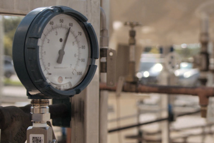
When a pressure indication is needed and an operator is around to see it, a traditional gauge offers a useful means to get the data, but drawbacks are possible.
While mechanical pressure gauges have been mainstays in the process industry, they have also brought some challenges with them. Still, when a situation calls for a simple and inexpensive device with a local display, a gauge can fit the bill in a variety of applications
Traditional gauges have some serious drawbacks to consider in the selection process. Gauges operate using delicate mechanisms with springs and gears, making them vulnerable to shock and damage . Most operators have seen typical failures with broken glass, bent indicator needles or needles pointing straight down from broken gearing. In many environments, they are considered essentially disposable because of their low cost and frequent failures.
Yet using pressure gauges is still a great way to visually show what is happening in the process. But wouldn’t it be nice to get that information to a centralized location without having to be physically present at the gauge? Old-fashioned clipboard rounds with operators writing down readings take time and can lead to inaccurate information resulting from human error.
Pressure gauges are still useful in many applications, and developments can extend their capabilities.
When a pressure indication is needed and an operator is around to see it, a traditional gauge offers a useful means to get the data, but drawbacks are possible.
While mechanical pressure gauges have been mainstays in the process industry, they have also brought some challenges with them. Still, when a situation calls for a simple and inexpensive device with a local display, a gauge can fit the bill in a variety of applications
Traditional gauges have some serious drawbacks to consider in the selection process. Gauges operate using delicate mechanisms with springs and gears, making them vulnerable to shock and damage . Most operators have seen typical failures with broken glass, bent indicator needles or needles pointing straight down from broken gearing. In many environments, they are considered essentially disposable because of their low cost and frequent failures.
Yet using pressure gauges is still a great way to visually show what is happening in the process. But wouldn’t it be nice to get that information to a centralized location without having to be physically present at the gauge? Old-fashioned clipboard rounds with operators writing down readings take time and can lead to inaccurate information resulting from human error.
Selection considerations
When a pressure indication is needed and an operator is around to see it, a traditional gauge offers a useful means to get the data, but drawbacks are possible.
The variety of traditional gauges continues to be massive, and key considerations require some analysis.
- Ruggedness – Some models are designed for environments in which pipes vibrate or moving equipment may cause impacts. Cases can be armored with rubber covers and beefed-up mechanisms to survive tough environments, but these options add cost.
- Material of construction – While the cheapest devices are mostly brass, industrial-grade gauges are usually made of stainless steel or other durable materials. Nonetheless, be sure to know what the wetted and nonwetted parts are made of. Brass or mild steel components can deteriorate in a humid or mildly corrosive atmosphere.
- Inlet configurations – Most larger gauges have a male-threaded inlet, usually ½-inch national pipe thread (NPT) or M20. Smaller and cheaper devices may be ¼-inch NPT. Usually the expectation is for screwing into an existing pressure port that has a female thread connection. Some offer more specialized options for more complex mounting situations, such as adding a siphon.
- Overpressure and burst pressure limits – These designations can be confusing. An overpressure limit says how much a unit can withstand without damage. In other words, it can take a spike and continue working properly. Beyond that, the Bourdon tube may be permanently distorted or the mechanism pushed past its limits. Burst pressure is where some component fails, usually the Bourdon tube, blowing the case open and releasing process fluid to the atmosphere, which can often be a safety risk. In some cases, the process connection itself fails and it can “launch the gauge” as a flying projectile. In the case where extra isolation is needed, such as using a seal for instance, this can add additional protection for the gauge. However, in the case of a failure, some units will still release the process fluid. If the substance is flammable or toxic, a safety incident will follow. Others are designed to try to contain a release or direct the release, although limits exist.
Accessories & special adaptations
The basic operating limitations of mechanical gauges have prompted the creation of a variety of supplementary devices to overcome some of the problems, so in some cases these may need to be added. Typical examples include:
- Snubber – This device restricts the gauge’s inlet pressure spikes and can serve two purposes: It can suppress pressure pulsations and it can improve overpressure protection. In either case, it is applied to the gauge’s inlet and tends to slow response.
- Isolator or seal – This device is designed to keep the process fluid from getting into the mechanism. It typically uses a combination of an external diaphragm, which contacts the process fluid and transmits the pressure to the mechanism using a captive fill fluid. Isolators are normally used in situations where products are hazardous or where temperatures are extremely high so the gauge is protected.
- Siphon – In situations where a gauge measures the pressure of a condensable vapor, usually steam, a siphon serves as a mechanism to trap condensate and act as a thermal barrier. The live steam places pressure on a slug of condensate in the siphon, which ends up acting as a fill fluid and keeps the device from seeing the full steam temperature.
Many other variations and special construction methods are designed to improve performance or avoid specific problems, including:
- Case fill fluid – Filling the gauge’s case with a viscous fluid, such as glycerin, helps reduce needle movement caused by pulsations.
- Heat tracing – In situations in which a device is exposed to cold environments, heating the case may be necessary.
- Blowout cases and safety glass – Where the possibility of a catastrophic failure is high, some devices are designed to fail and release fragments and fluid in a single direction, usually out the back of the gauge, presumably away from people.
If an application depends on some of these more elaborate precautions, it is probably advisable to investigate some of the new technology improvements available for the industry.
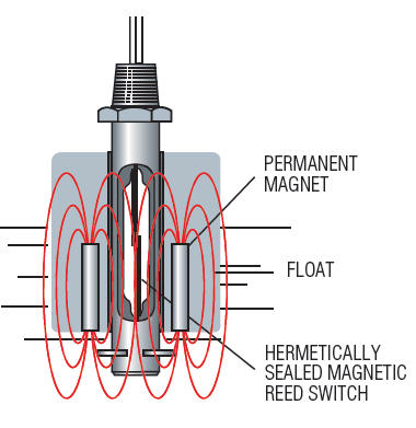
 The necessity of having a tube flex in response to pressure change and tying it to a gear mechanism makes for a delicate device easily subject to damage.
The basic operating limitations of mechanical gauges have prompted the creation of a variety of supplementary devices to overcome some of the problems, so in some cases these may need to be added. Typical examples include:
- Snubber – This device restricts the gauge’s inlet pressure spikes and can serve two purposes: It can suppress pressure pulsations and it can improve overpressure protection. In either case, it is applied to the gauge’s inlet and tends to slow response.
- Isolator or seal – This device is designed to keep the process fluid from getting into the mechanism. It typically uses a combination of an external diaphragm, which contacts the process fluid and transmits the pressure to the mechanism using a captive fill fluid. Isolators are normally used in situations where products are hazardous or where temperatures are extremely high so the gauge is protected.
- Siphon – In situations where a gauge measures the pressure of a condensable vapor, usually steam, a siphon serves as a mechanism to trap condensate and act as a thermal barrier. The live steam places pressure on a slug of condensate in the siphon, which ends up acting as a fill fluid and keeps the device from seeing the full steam temperature.
Many other variations and special construction methods are designed to improve performance or avoid specific problems, including:
- Case fill fluid – Filling the gauge’s case with a viscous fluid, such as glycerin, helps reduce needle movement caused by pulsations.
- Heat tracing – In situations in which a device is exposed to cold environments, heating the case may be necessary.
- Blowout cases and safety glass – Where the possibility of a catastrophic failure is high, some devices are designed to fail and release fragments and fluid in a single direction, usually out the back of the gauge, presumably away from people.
If an application depends on some of these more elaborate precautions, it is probably advisable to investigate some of the new technology improvements available for the industry.
The necessity of having a tube flex in response to pressure change and tying it to a gear mechanism makes for a delicate device easily subject to damage.
Basic design improvements
Since the user case for a basic gauge is still valid, various companies have tried to improve the design without losing the underlying appeal.
- Digital gauges – Some companies have developed ways to retain the basic Bourdon tube design but replace the moving needle with a digital display. While the concept is good, the execution often suffers from visibility problems and short battery life. These are not normally practical for a device that is expected to run continuously, so they are often reserved for calibration lab and testing duties where they can be turned on and off when needed.
- Electronic gauges – Some of the newest designs combine the benefits of an electronic transmitter with the usefulness of a traditional mechanical design. They use a strain-relief sensor rather than a Bourdon tube, processing the signal electronically rather than mechanically. The needle is driven by a tiny motor, so only one moving part is present, making the mechanism far more resistant to shocks and other extreme operating conditions.
Electronic gauges avoid many of the problems of mechanical devices. Eliminating the Bourdon tube removes a critical failure point, so overpressure capability is much higher and the possibility for process fluid escape is far lower. Many of the accessories necessary to ensure good performance are also no longer needed since those capabilities are part of the basic design of the new units.
Using sophisticated electronics, these new gauges are also able to monitor their own statuses. No way exists to verify a mechanical gauge is working properly short of removal from the process and testing, but a glance at an electronic gauge can show its operational status by a blinking LED. Even the battery life has been extended thanks to low-power electronics and highly efficient designs.
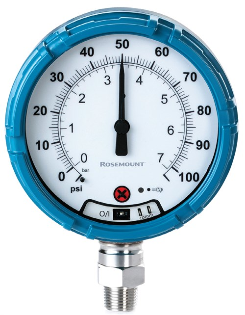 Wireless pressure gauges, like this model, serve as practical hybrids, incorporating many of the safety and performance advantages of electronic transmitters while providing effective local displays.
In many respects, the most critical drawback of a traditional gauge, its inability to send information to an automation system, has been overcome because these new devices include wireless transmitters able to send the pressure reading and status indications to the distributed control system or other automation platform. This optional function can be used whenever necessary.
One wireless pressure gauge (see Image 2) contains all the features of an electronic gauge while adding the capability to transmit its pressure reading via a WirelessHART mesh network. This additional communication capability adds “future-proofing” so it can be used in a sophisticated networking environment as the Industrial Internet of Things moves into more manufacturing applications. The wireless capability might not be needed today, but it may be soon.
Because this wireless pressure gauge is equipped with an advanced sensor design and additional isolator, it does not require a snubber. Its internal integral sensor isolator also keeps the process fluid from ever reaching the sensor, extending its working temperature range. Since it does not require a special configuration or other accessories, it is often a lower cost option than a traditional gauge in demanding applications.
Wireless pressure gauges, like this model, serve as practical hybrids, incorporating many of the safety and performance advantages of electronic transmitters while providing effective local displays.
In many respects, the most critical drawback of a traditional gauge, its inability to send information to an automation system, has been overcome because these new devices include wireless transmitters able to send the pressure reading and status indications to the distributed control system or other automation platform. This optional function can be used whenever necessary.
One wireless pressure gauge (see Image 2) contains all the features of an electronic gauge while adding the capability to transmit its pressure reading via a WirelessHART mesh network. This additional communication capability adds “future-proofing” so it can be used in a sophisticated networking environment as the Industrial Internet of Things moves into more manufacturing applications. The wireless capability might not be needed today, but it may be soon.
Because this wireless pressure gauge is equipped with an advanced sensor design and additional isolator, it does not require a snubber. Its internal integral sensor isolator also keeps the process fluid from ever reaching the sensor, extending its working temperature range. Since it does not require a special configuration or other accessories, it is often a lower cost option than a traditional gauge in demanding applications.
Since the user case for a basic gauge is still valid, various companies have tried to improve the design without losing the underlying appeal.
- Digital gauges – Some companies have developed ways to retain the basic Bourdon tube design but replace the moving needle with a digital display. While the concept is good, the execution often suffers from visibility problems and short battery life. These are not normally practical for a device that is expected to run continuously, so they are often reserved for calibration lab and testing duties where they can be turned on and off when needed.
- Electronic gauges – Some of the newest designs combine the benefits of an electronic transmitter with the usefulness of a traditional mechanical design. They use a strain-relief sensor rather than a Bourdon tube, processing the signal electronically rather than mechanically. The needle is driven by a tiny motor, so only one moving part is present, making the mechanism far more resistant to shocks and other extreme operating conditions.
Electronic gauges avoid many of the problems of mechanical devices. Eliminating the Bourdon tube removes a critical failure point, so overpressure capability is much higher and the possibility for process fluid escape is far lower. Many of the accessories necessary to ensure good performance are also no longer needed since those capabilities are part of the basic design of the new units.
Using sophisticated electronics, these new gauges are also able to monitor their own statuses. No way exists to verify a mechanical gauge is working properly short of removal from the process and testing, but a glance at an electronic gauge can show its operational status by a blinking LED. Even the battery life has been extended thanks to low-power electronics and highly efficient designs.
Wireless pressure gauges, like this model, serve as practical hybrids, incorporating many of the safety and performance advantages of electronic transmitters while providing effective local displays.
In many respects, the most critical drawback of a traditional gauge, its inability to send information to an automation system, has been overcome because these new devices include wireless transmitters able to send the pressure reading and status indications to the distributed control system or other automation platform. This optional function can be used whenever necessary.
One wireless pressure gauge (see Image 2) contains all the features of an electronic gauge while adding the capability to transmit its pressure reading via a WirelessHART mesh network. This additional communication capability adds “future-proofing” so it can be used in a sophisticated networking environment as the Industrial Internet of Things moves into more manufacturing applications. The wireless capability might not be needed today, but it may be soon.
Because this wireless pressure gauge is equipped with an advanced sensor design and additional isolator, it does not require a snubber. Its internal integral sensor isolator also keeps the process fluid from ever reaching the sensor, extending its working temperature range. Since it does not require a special configuration or other accessories, it is often a lower cost option than a traditional gauge in demanding applications.
Matching device & application
This new range of options means it is possible to choose exactly the item needed for a given situation and budget.
- Traditional mechanical gauge – Where the process is benign, the budget limited, and a local reading and moderate precision fill the bill.
- Electronic pressure transmitter – For more extreme applications, in an automated environment and in which the highest precision is necessary, but it is the most expensive.
- Wireless pressure gauge – This new choice fills many of the areas in between. The process and safety parameters can be more challenging, and options exist to communicate wirelessly with the plant systems, today and tomorrow. The price falls between the other two options, providing a useful new process solution.
Pressure gauge technology continues to advance, providing more choices and enabling end users to measure this important process parameter in an optimal fashion.